
 EN
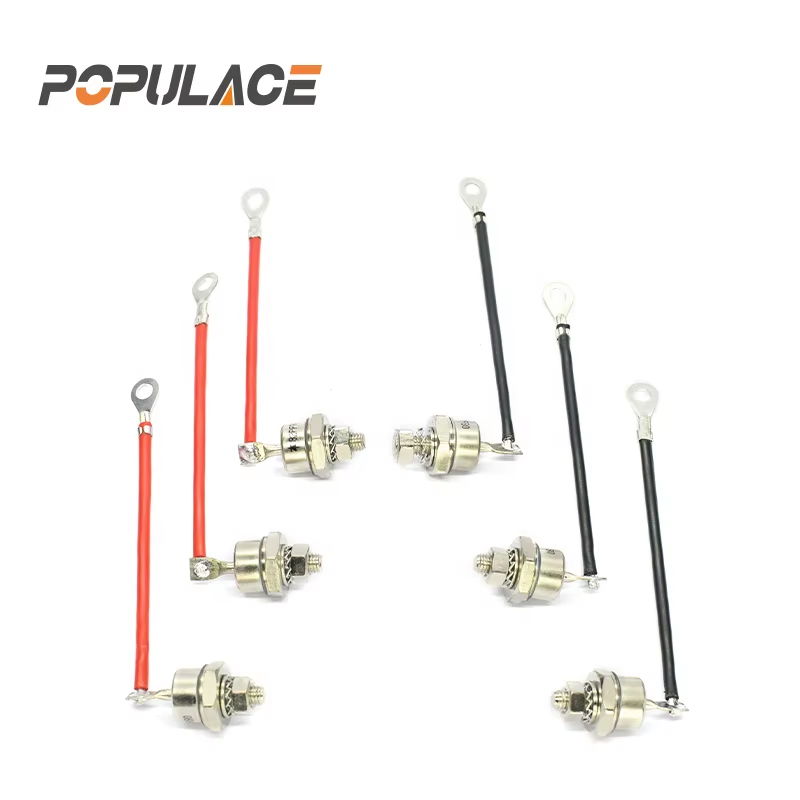
How to Troubleshoot Generator AVR Issues Caused by a Faulty 3 Phase Bridge Rectifier
When a brushless generator has unstable voltage, no build-up, or voltage that collapses as load changes, the AVR is often blamed first. That is understandable, but it can send a technician in the wrong direction. In many brushless machines, the AVR may be commanding excitation correctly while a faulty 3 phase bridge rectifier on the rotating assembly prevents that excitation from reaching the main rotor as clean DC.
From a genset maintenance perspective, the useful question is not simply “Is the AVR bad?” It is whether the excitation path is intact from the AVR output through the exciter stator, exciter rotor, generator rotating rectifier, and main rotor. A disciplined check prevents unnecessary AVR replacement and makes the final repair easier to verify.
Why a 3 Phase Bridge Rectifier Can Look Like an AVR Failure
In a typical brushless alternator, the AVR feeds the stationary exciter field. The exciter rotor then produces three-phase AC. A rotating 3 phase rectifier bridge converts that AC to DC for the main rotor field. The main stator can then produce the controlled output voltage seen at the generator terminals.
If one diode in the bridge opens, shorts, or becomes intermittent with heat and vibration, the main rotor receives poor-quality or incomplete field current. The result may resemble a control problem: low voltage, wandering voltage, slow recovery after a load step, excessive ripple, or a machine that seems to work unloaded but fails when a meaningful load is applied. A defective 3 phase diode rectifier can therefore be the root cause even when the AVR appears to be active.
The important distinction is that an AVR senses and corrects voltage, while the rotating diode pack transfers exciter energy to the main field. Replacing the controller without proving the transfer path is a common and expensive detour.
Start With Safe Isolation and a Symptom Record
Lock out the generator, prevent automatic starting, and follow the manufacturer’s procedures before removing covers or measuring resistance. Rotating assemblies, stored energy, and live test conditions create real hazards. If your site requires energized checks, use a qualified technician and the approved test method for that alternator.
Before disconnecting anything, record the operating symptom. Note terminal voltage with no load and under a controlled load, engine speed or frequency, AVR output if the manufacturer permits measurement, alarms, recent moisture exposure, surge events, and any work performed on the alternator. This short record matters because it helps separate an excitation fault from an engine-speed or sensing problem.
- Low voltage with stable frequency: investigate the excitation chain before assuming the engine is at fault.
- Voltage hunting with normal mechanical speed: inspect AVR sensing and wiring, then check the rectifier and exciter circuit.
- Voltage that disappears or drops sharply under load: look for a weak diode, loose rotating connection, or heat-sensitive joint.
- Repeated diode failure: do not stop at the diode pack; investigate surge suppression, winding condition, cooling, contamination, and connection torque.
Rule Out the Easy Causes Before Opening the Rectifier Assembly
Check speed and frequency first. An AVR cannot compensate for an engine that is materially off speed, because output frequency and voltage regulation are linked to machine conditions. Then inspect the AVR sensing leads, fuses, connectors, and any remote-voltage-adjustment circuit. Verify that the machine’s configuration, sensing range, and replacement parts match the alternator model.
Next, inspect for heat discoloration, moisture tracks, loose terminals, damaged insulation, or carbon dust. A bridge rectifier 3 phase assembly is mounted on a rotating structure, so a connection that looks acceptable while stationary can still be unreliable under centrifugal force or vibration. Early in troubleshooting, many teams focus only on voltage ratings. After a failed installation, the focus usually shifts to sensing input type, diode orientation, torque, insulation condition, and the exact rotating assembly layout.

How to Test the Generator Rotating Rectifier
Use the alternator manufacturer’s diagram to identify the diode pack and its terminals. Photograph and label connections before disturbing them. The exact access method differs by frame and alternator design, but the principle is the same: each diode in the 3 phase bridge rectifier should conduct in one direction and block in the other.
- Isolate the diode under test. Where the manufacturer requires it, disconnect at least one lead so parallel winding paths do not create a misleading reading. Do not force a universal in-circuit method onto a design that needs isolated testing.
- Use the meter’s diode function. Test one direction, reverse the probes, and compare the behavior. A healthy diode normally shows a forward-conduction indication in one direction and an open or blocking indication in the reverse direction. Follow the meter and OEM instructions rather than relying on one generic numeric value.
- Compare like parts. In a 3 phase rectifier bridge, compare the three positive-side diodes with one another and the three negative-side diodes with one another. A result that differs sharply from comparable devices deserves investigation.
- Look beyond the diode body. Check mounting hardware, heat-sink contact, terminals, leads, and insulating washers. A reversed diode, damaged insulator, or loose terminal can produce the same symptom as a failed semiconductor.
- Check the associated windings. If all diodes test consistently, continue with exciter rotor and field-winding checks according to the OEM data. The rectifier may be innocent while the exciter source is weak or interrupted.
Do not use a high-voltage insulation tester across semiconductor devices unless the manufacturer specifically instructs you to do so. That test can damage parts or produce conclusions that do not identify the actual fault.
Interpreting Common Results
| Finding | What it suggests | Next action |
|---|---|---|
| Conducts both directions | Shorted diode or an unintended parallel path | Isolate the lead and retest; replace the confirmed defective device or approved assembly. |
| Blocks both directions | Open diode, broken lead, or poor meter connection | Verify probe contact and isolation; compare with matching diodes. |
| One diode reads unlike its peers | Likely weak or failed component | Confirm polarity and part identification before replacement. |
| All diodes appear normal but voltage is poor | Possible exciter, AVR sensing, wiring, residual magnetism, or main-field issue | Return to the OEM excitation-path test sequence. |
Replacement and Recommissioning Checks
Use only a replacement specified for the alternator or a verified equivalent with the correct electrical and mechanical characteristics. “Similar” diode modules can differ in current capability, reverse-voltage rating, polarity layout, mounting, and thermal performance. A maintenance engineer should confirm the alternator model, rectifier part reference, diode orientation, and connection diagram before an order is released.
During assembly, clean the mounting surfaces, use the specified torque, replace damaged hardware or insulation components, and ensure no lead can chafe against the rotor. If your priority is reliable recovery after repair, the most relevant factor is not the lowest component price; it is verified compatibility and a documented installation sequence.
After reassembly, commission the generator in stages: confirm no-load voltage and frequency, apply a controlled load, observe voltage recovery and stability, and recheck for abnormal heating or alarms. Record the result so future troubleshooting can compare the machine’s behavior to a known good baseline.
When the AVR Still Needs Attention
A sound 3 phase bridge rectifier does not automatically clear the AVR. If the diode pack and winding checks are consistent, examine AVR supply, sensing inputs, trim settings, protection circuits, and model compatibility. Whether repair or replacement is appropriate depends on the alternator design, fault evidence, and site requirements,there is no single right answer.
For recurring maintenance, keep the alternator diagram, approved part references, prior test records, and installation notes together. That simple practice turns a difficult AVR complaint into a repeatable excitation-path diagnosis and reduces the chance that a faulty generator rotating rectifier is mistaken for a controller failure.





